
Smooth Voxel Terrain in Babylon.js · Part 3 of 12 in the series
Part 3: Surface Nets
Add a second mesher that needs no table: one vertex inside each cell the surface passes through, and a quad across each edge where the density changes sign. The M key switches between the two.
Quest objectives
- Know how surface nets differ from marching cubes
- Place one vertex per cell, at the average of the points where its edges cross the surface
- Join the vertices with a quad across every edge that changes sign
- Mesh one cell more than the chunk has, and take only the edges the chunk owns
- Put both meshers behind one interface and switch between them
Marching cubes, from part 2, puts its vertices on the grid's edges and needs a table to connect them. Surface nets turn it around: one vertex inside each cell that the surface passes through, and the faces between them come straight from the grid, without any table. Sarah Gibson described them in 1998; games use a simple form of them, which this part builds.
The idea
Every cell with solid and air corners gets a vertex. Where in the cell? The cell's edges that change sign each cross the surface at one point, worked out the same way as in marching cubes. The vertex goes to the average of those points. That is not exactly on the surface, but close to it, and it moves smoothly from cell to cell.
Then the faces. Take an edge of the grid whose two samples have different signs: the surface passes through it. Four cells share that edge, the ones around it, and each of them has a vertex, because each has that edge with its sign change. Those four vertices make a quad, and the quad crosses the edge. One quad per crossed edge, and the surface is complete.
Which way the quad faces follows from which end of the edge is solid: its front goes towards the air.
One cell more
The four cells around an edge on the chunk's border lie partly outside the chunk. Part 5 cuts the terrain into many chunks, and they have to meet without a gap, so this part already meshes the way that works there:
The chunk makes vertices in cells 0 to 32 on each axis: one cell more than it has, reaching into the next chunk.
Of the edges along an axis, the chunk takes those that start at 0 to 31 along it and at 1 to 32 on the two other axes. Then the four cells around each of its edges are among its 33 cells. The edges at 0 on the other axes belong to the chunk below, which takes them as its 32.
Each edge of the world then belongs to exactly one chunk, and the vertices in the shared cells come out the same in both chunks, because they are worked out from the same samples.
Cell 32 has corners at 33, and its normal, below, needs the gradient there, which needs the sample at 34. So the margin grows to two samples. In src/grid.ts, change MARGIN:
/**
 * Extra samples around the cells on every side. The normals need one sample beyond the
 * edge, and the last cells of surface nets reach one sample further.
 */
export const MARGIN = 2;
Quads
A quad is drawn as two triangles, split along one of its diagonals. The four vertices rarely lie in one plane, and the shorter diagonal gives the better pair: the longer one would make a crease where the surface is bent. Add a method to MeshBuilder in src/meshData.ts, under triangle():
/** Two triangles for the four corners, split along the shorter diagonal. */
quad(a: number, b: number, c: number, d: number): void {
  if (this.distance(a, c) <= this.distance(b, d)) {
    this.triangle(a, b, c);
    this.triangle(a, c, d);
  } else {
    this.triangle(b, c, d);
    this.triangle(b, d, a);
  }
}

private distance(a: number, b: number): number {
  const p = this.positions;
  return Math.hypot(p[a * 3] - p[b * 3], p[a * 3 + 1] - p[b * 3 + 1], p[a * 3 + 2] - p[b * 3 + 2]);
}
Surface nets
Create src/surfaceNets.ts:
import { CHUNK_SIZE, type DensityGrid } from './grid.ts';
import { MeshBuilder, type MeshData } from './meshData.ts';

/** The eight corners of a cell, numbered like the marching cubes corners. */
const CORNERS = [
  [0, 0, 0], [1, 0, 0], [0, 1, 0], [1, 1, 0],
  [0, 0, 1], [1, 0, 1], [0, 1, 1], [1, 1, 1],
];
/** The twelve edges of a cell, as the corners they join. */
const EDGES = [
  [0, 1], [2, 3], [4, 5], [6, 7],
  [0, 2], [1, 3], [4, 6], [5, 7],
  [0, 4], [1, 5], [2, 6], [3, 7],
];

const lerp = (a: number, b: number, t: number) => a + (b - a) * t;

/**
 * A surface for the density with one vertex in each cell the surface passes through, and
 * a quad across each edge of the grid where the density changes sign. The quad joins the
 * vertices of the four cells around that edge.
 */
export function surfaceNets(grid: DensityGrid): MeshData {
  const mesh = new MeshBuilder();
  // Cells 0 to CHUNK_SIZE: one more on each axis than the chunk has, see below.
  const cells = CHUNK_SIZE + 1;
  const vertexIn = new Int32Array(cells ** 3).fill(-1);
  const step = [1, cells, cells * cells];
  const d = new Float32Array(8);

  for (let z = 0; z < cells; z += 1) {
    for (let y = 0; y < cells; y += 1) {
      for (let x = 0; x < cells; x += 1) {
        let solid = 0;
        for (let c = 0; c < 8; c += 1) {
          d[c] = grid.get(x + CORNERS[c][0], y + CORNERS[c][1], z + CORNERS[c][2]);
          if (d[c] > 0) solid += 1;
        }
        if (solid === 0 || solid === 8) continue;

        // The vertex sits at the average of the points where the edges cross the surface.
        let px = 0;
        let py = 0;
        let pz = 0;
        let crossings = 0;
        for (const [a, b] of EDGES) {
          if (d[a] > 0 === d[b] > 0) continue;
          const t = d[a] / (d[a] - d[b]);
          px += lerp(CORNERS[a][0], CORNERS[b][0], t);
          py += lerp(CORNERS[a][1], CORNERS[b][1], t);
          pz += lerp(CORNERS[a][2], CORNERS[b][2], t);
          crossings += 1;
        }
        px /= crossings;
        py /= crossings;
        pz /= crossings;

        // The normal: the corners' gradients, blended by how close the vertex is to each.
        let nx = 0;
        let ny = 0;
        let nz = 0;
        for (let c = 0; c < 8; c += 1) {
          const [cx, cy, cz] = CORNERS[c];
          const weight = (cx ? px : 1 - px) * (cy ? py : 1 - py) * (cz ? pz : 1 - pz);
          const [gx, gy, gz] = grid.gradient(x + cx, y + cy, z + cz);
          nx -= gx * weight;
          ny -= gy * weight;
          nz -= gz * weight;
        }
        vertexIn[x + y * step[1] + z * step[2]] = mesh.vertex(x + px, y + py, z + pz, nx, ny, nz);
      }
    }
  }

  // A quad for every edge with a sign change. Of the edges along an axis, the chunk takes
  // those 0 to CHUNK_SIZE - 1 along it and 1 to CHUNK_SIZE on the other two axes, so that
  // the four cells around each edge are among its cells. The neighbors take the rest.
  for (let z = 0; z <= CHUNK_SIZE; z += 1) {
    for (let y = 0; y <= CHUNK_SIZE; y += 1) {
      for (let x = 0; x <= CHUNK_SIZE; x += 1) {
        const p = [x, y, z];
        const here = grid.get(x, y, z) > 0;
        const cell = x + y * step[1] + z * step[2];
        for (let axis = 0; axis < 3; axis += 1) {
          const u = (axis + 1) % 3;
          const v = (axis + 2) % 3;
          if (p[axis] === CHUNK_SIZE || p[u] === 0 || p[v] === 0) continue;
          const there = grid.get(x + (axis === 0 ? 1 : 0), y + (axis === 1 ? 1 : 0), z + (axis === 2 ? 1 : 0)) > 0;
          if (here === there) continue;

          // The four cells around the edge, in order around it.
          const a = vertexIn[cell - step[u] - step[v]];
          const b = vertexIn[cell - step[v]];
          const c = vertexIn[cell];
          const e = vertexIn[cell - step[u]];
          // Which way the quad faces depends on which end of the edge is solid.
          if (here) mesh.quad(a, e, c, b);
          else mesh.quad(a, b, c, e);
        }
      }
    }
  }
  return mesh.build();
}
The first pass makes the vertices.
vertexInremembers each cell's vertex, -1 where there is none, in a flat array of 333 cells.The normal blends the gradients at the cell's eight corners. Each corner's weight is how close the vertex is to it, the same weights a trilinear blend uses: a vertex in the middle of the cell takes all eight equally, one right next to a corner takes mostly that corner's.
The second pass goes over the samples and their three edges towards higher x, y and z. The
continuekeeps the edges the chunk owns, and the sign test the edges that cross the surface.stepis how far a cell's number jumps for one step on each axis, so the four cells around an edge are the current cell and three neighbors one step back.
Two meshers, one interface
Both meshers take a grid and return a MeshData, so the rest of the code doesn't need to know which one it has. Create src/meshers.ts:
import type { DensityGrid } from './grid.ts';
import { marchingCubes } from './marchingCubes.ts';
import type { MeshData } from './meshData.ts';
import { surfaceNets } from './surfaceNets.ts';

/** Both ways to turn a grid into a mesh, by name. */
export const MESHERS = {
  'marching-cubes': { label: 'Marching cubes', mesh: marchingCubes },
  'surface-nets': { label: 'Surface nets', mesh: surfaceNets },
} satisfies Record<string, { label: string; mesh: (grid: DensityGrid) => MeshData }>;

export type MesherName = keyof typeof MESHERS;

/** The other mesher. */
export function otherMesher(name: MesherName): MesherName {
  return name === 'marching-cubes' ? 'surface-nets' : 'marching-cubes';
}
satisfies checks the object against the type without changing it: MesherName is still exactly the two names. Later parts send the name to Web Workers, which can't receive functions.
Replace src/main.ts. It meshes with the current mesher, measures the time, and builds again on M. Because this part is about surface nets, they come first:
import {
  ArcRotateCamera,
  Color3,
  Color4,
  DirectionalLight,
  Engine,
  HemisphericLight,
  RegisterStandardEngineExtensions,
  RegisterStandardMaterial,
  RegisterThinInstanceMesh,
  Scene,
  StandardMaterial,
  Vector3,
  type Mesh,
} from '@babylonjs/core/pure';
import { showBlocks } from './blocks.ts';
import { CHUNK_SIZE, DensityGrid } from './grid.ts';
import { createMesh } from './meshData.ts';
import { MESHERS, otherMesher, type MesherName } from './meshers.ts';
import { testShape } from './shapes.ts';
import './style.css';

RegisterStandardEngineExtensions();
RegisterStandardMaterial();
RegisterThinInstanceMesh();

const canvas = document.querySelector<HTMLCanvasElement>('#game')!;
const hud = document.querySelector<HTMLElement>('#hud')!;

const engine = new Engine(canvas, true, {}, true);
const scene = new Scene(engine);
scene.clearColor = Color4.FromHexString('#2a1150ff');

// A cool light from the sky and a warm, low sun.
const sky = new HemisphericLight('sky', new Vector3(0, 1, 0), scene);
sky.intensity = 0.6;
sky.diffuse = Color3.FromHexString('#c4b5fd');
sky.groundColor = Color3.FromHexString('#3b1676');
const sun = new DirectionalLight('sun', new Vector3(0.5, -0.65, -0.55), scene);
sun.intensity = 1.1;
sun.diffuse = Color3.FromHexString('#ffd8a8');

const grid = new DensityGrid().fill(testShape);
const material = new StandardMaterial('ground', scene);
material.diffuseColor = Color3.FromHexString('#d9a066');
material.specularColor = Color3.Black();

// This part is about surface nets, so they come first; M switches to marching cubes.
let mesher: MesherName = 'surface-nets';
let mesh: Mesh | null = null;

/** Meshes the grid with the current mesher, in place of the last mesh. */
function remesh(): void {
  const started = performance.now();
  const data = MESHERS[mesher].mesh(grid);
  const time = performance.now() - started;
  mesh?.dispose();
  mesh = createMesh('shape', data, scene);
  mesh.material = material;
  hud.textContent =
    `${MESHERS[mesher].label} in ${time.toFixed(1)} ms\n` +
    `${data.indices.length / 3} triangles, ${data.positions.length / 3} vertices`;
}
remesh();

const blocks = showBlocks(scene, grid);
blocks.setEnabled(false);

window.addEventListener('keydown', (event) => {
  if (event.code === 'KeyB') blocks.setEnabled(!blocks.isEnabled());
  if (event.code === 'KeyL') material.wireframe = !material.wireframe;
  if (event.code === 'KeyM') {
    mesher = otherMesher(mesher);
    remesh();
  }
});

// Orbit around the middle of the grid.
const middle = new Vector3(CHUNK_SIZE / 2, CHUNK_SIZE / 3, CHUNK_SIZE / 2);
const camera = new ArcRotateCamera('camera', 2.2, 1.1, 60, middle, scene);
camera.attachControl();
camera.lowerRadiusLimit = 10;
camera.upperRadiusLimit = 120;
camera.wheelPrecision = 5;

engine.runRenderLoop(() => scene.render());
window.addEventListener('resize', () => engine.resize());
In index.html, add M mesher to the help, before B blocks.
Try it
At first sight the shape looks the same as in part 2. Press L: the triangles are more even. Marching cubes makes slivers where the surface passes close to a sample; surface nets make pairs of triangles of about the same size, which follow the grid in rows.
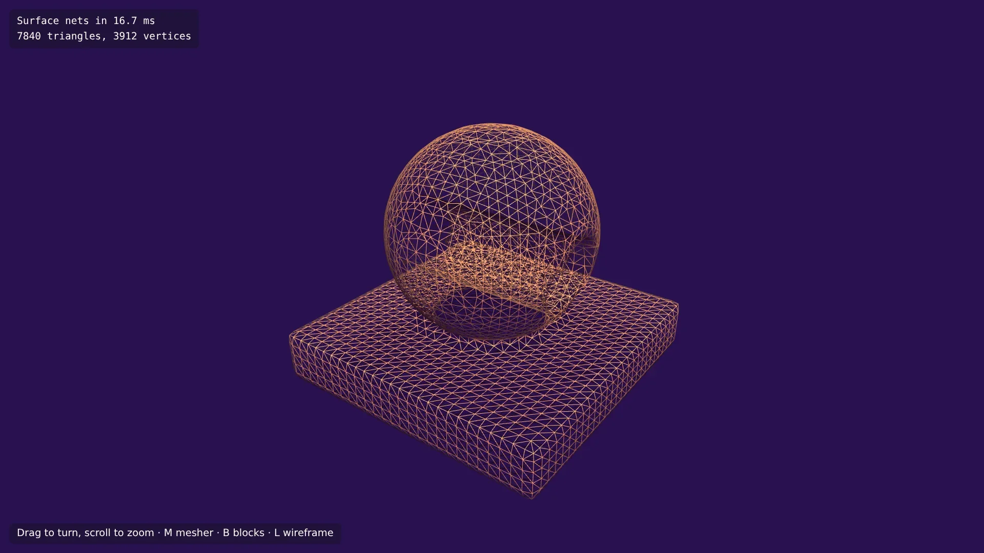
Press M a few times and compare. On this shape both meshes have 7,840 triangles, but they are not the same:
Marching cubes' vertices lie exactly where the density crosses 0 along an edge. Surface nets' vertices are averages, so curves come out a little rounder and the tunnel's rim a little softer. Neither keeps the sharp edge.
Surface nets have no table and no cases, and their triangles are better shaped. Marching cubes, in return, keeps every vertex on the surface that the samples describe.
Here surface nets take longer, because each vertex blends eight gradients where marching cubes blends two. The time in the HUD changes from build to build: the browser compiles the code faster after the first runs.
Both are good choices for terrain, which is why the series keeps both. You'll see them on real terrain in the next part.
In the next part the test shape makes way for terrain: hills, mountains, overhangs and caves from noise.